
Georeferencing
With drone photogrammetry becoming more and more popular and easier to perform, a few important things must be kept in mind when producing 3D models, especially if the requested output is used for high accuracy measurements.
When working solely with the drone’s internal GPS (and not RTK system), images are georeferenced with an error ranging between 1 to 4m to the true position. The error is due to deviations of the signal in the atmosphere, the quality of the receiver’s internal clock, number of satellites, signal multipath, and orbit errors. Fortunately this error is more or less systematic for a given time and location, all the pictures for a specific scan have about the same shift.
This means that the outputs such as the orthophoto will be shifted with the mean error between all the geotags. For the DEM however, things are slightly more complicated, as without the use of controls points systematic calculations errors can appear during reconstruction. More on that later.
If the orthophoto is used in an arbitrary coordinate system, or if no accurate comparison with other georeferenced data (this includes later scan of the same area) are planned, then things are perfectly fine and no further processing is required.
Otherwise, introduction of ground control points, or usage of a drone equipped with RTK system is mandatory
A note on the difference between GPS accuracy and precision:
- GPS accuracy: The accuracy refers to the degree of closeness the indicated readings are to the actual position.
- GPS precision: Is the degree to which the readings can be made. The smaller the circle of unknown the higher the precision.
Model resolution and accuracy
Inside a model you must distinguish between resolution and accuracy.
Resolution is only dependent on the flight height above the ground and camera parameters (sensor size and focal length) and is generally measured in cm per pixel. Usually the resolution is between 1 to 3 cm/pixel with consumer drones flying between 30 and 50m above ground
Accuracy however depends on the flight height, quality of the camera (lens deformation, rolling shutter,…) the type of surface surveyed, and flight planning.
Obtaining information about the accuracy of the model is only possible by having validation points. What is usually done is to evaluate the quality of a camera and optimal flight planning before field acquisition, as putting validation points during each field campaign is nearly impossible and only done for projects that require the highest accuracy.

Classic photogrammetry errors
Now what are these systematic calculations errors introduced by the software and how can careful flight planning improve the quality of the results?
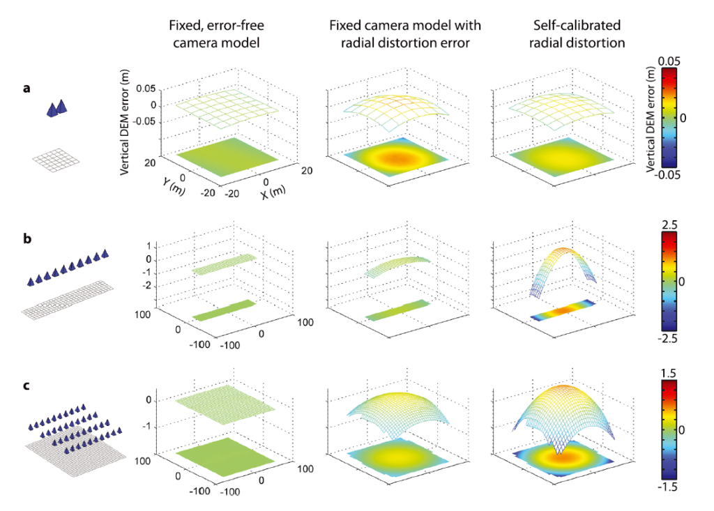
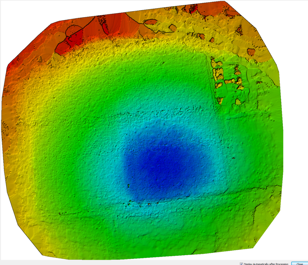
Flying a drone around taking pictures in a gridded pattern and then launching the processing without any user-inputs will result in the introduction of typical systematic photogrammetry errors such as doming and tilt
With a single gridded flight pattern, images are acquired in a linear pattern along a flight line forming ‘strips’, parallel flight lines form overlapping ‘strips’, which then form ‘image blocks’ of survey areas. If systematic errors persist from strips to the block, then resulting DEM will contain the same deformation (James and Robson, 2014)
These systematic errors will be especially severe when using consumer grade equipment with wide angle – high radial deformation lenses, with the addition of self-calibration procedures
To correct for such deformations, conjunction of two techniques is required: Ground Control Points (GCPs) and a more advancedflight pattern
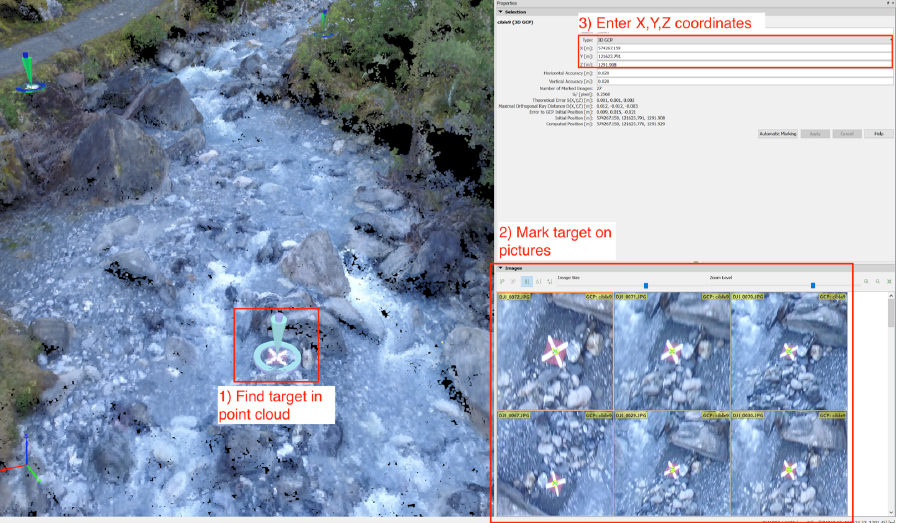
Ground Control Points consist of specific target points measured with great accuracy (<2cm), which must be well visible on the drone images for later marking in the processing software.
Drone internal GPS systems are not very accurate and may result in an offset of ±2m in the horizontal axis and ±5m in the vertical axis. Consequently the inclusion of Ground Control Points allows to correctly reference the resulting models, thus permitting accurate comparisons with other georeferenced data.
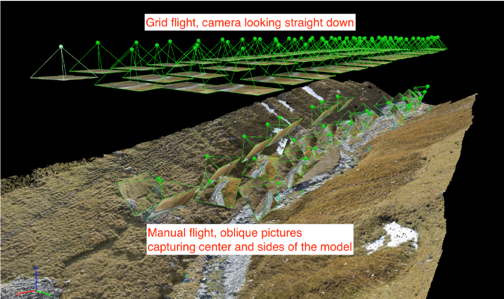
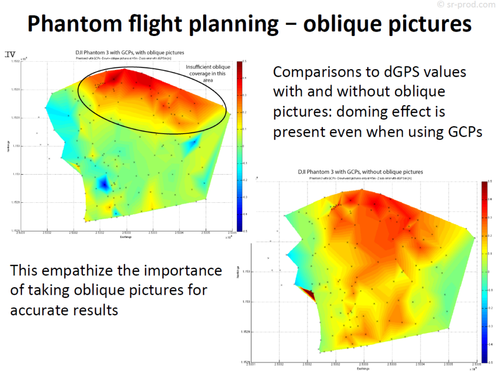
Testing showed that best results are acquired with a more complex flight pattern. This advanced flight planning requires to first perform a gridded flight over the entire survey area with the camera looking fully downward. Once done, capture oblique pictures with the camera at around 45° capturing the survey area at various angles, this should be performed in manual flight mode